

Here are easy steps to wire a 7 pin trailer plug with the electric brakes. There are standard 4-pin, 5-pin, and 7-pin connectors available to provide indicator lights and fulfill electric brakes’ requirements from towing vehicles.
How to Wire a 7 Pin Trailer Plug With Electric Brakes? Blue wire in the 7-pin trailer plug connects with the electric brakes with the output of the brake controller in a towing vehicle. White wire provides ground for completion of the circuit. Install all the cables of appropriate gauge, tucked with trailer frame in protective covering to ensure the proper functioning of electric brakes.
A safe and reliable wiring arrangement is necessary to power up the electric brakes and their control from towing vehicles.
According to various state laws, towed vehicles weighing 2800-3200 lbs require electric brakes on the single axle or both axles.
How to Wire a 7 Pin Trailer Plug With Electric Brakes?
A 7-pin connector is suitable for large trailers and RVs with more wiring options.
Each wire has specific color according to the standard for a particular function. However, you can modify the wiring according to your requirements.
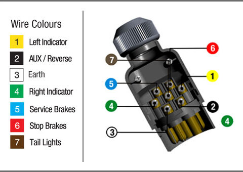
Color coding of 7 pin connector
There are seven colored wires in a 7-pin connector both on the vehicle side and trailer side.
According to the RV standard, the colors included are white, brown, green, yellow, blue, red, and black.
| Wire Color | Wire Connects With |
| Yellow | Left indicator |
| Black | AUX / Reverse |
| White | Earth |
| Green | Right indicator |
| Blue | Electric Brakes |
| Red | Brakes |
| Brown | Tail light |
However, the SAE standard has a purple-colored wire instead of black. They use Red and Black interchangeably for 12V battery power.
Our particular concern is for wiring electric brakes on its side with a 7-pin plug. Specific colored wire dedicated for the purpose is the blue one in both standards.
You will find the blue-colored wire connected with the brake controller power output on the vehicle side.
Electric brakes wiring for single axle trailer
Single axle trailers have less weight loading capacity, and electric brakes installed on them also vary accordingly.
You need to connect these on both wheels with the same blue-colored wire to ensure a unified braking operation of both wheels.
Moreover, to ensure safe operation in broken wire with one side, both brakes must be connected in parallel combination.
Extend a single wire up to the axle and splice it into two wires to connect with the one terminal of the coil of the electromagnet in the brakes.
Connect its other side with the standard white ground wire for all purposes, including lights and brakes.
To prevent later problems due to malfunctioning of ground wire, ensure to run it throughout the periphery of the trailer and connect the brakes with it instead of the metallic frame of the camper.
Wire Connection in Tandem Axle Trailers
In the case of tandem axle trailers, it is recommended to use electric brakes on both axles. In this way, you need to make connections with four brake assemblies on all wheels.
Each of them requires a pair of wires for 12V power using blue wire and white ground wire.
Install a wire of appropriate gauge from the 7-pin connector to both the brakes on the left side and then splice it and install a jumper wire to power up the assemblies on the other side of the trailer.
Connect the other terminal of all electromagnets with the ground wire. You can connect it with the trailer’s frame; however, it can lead to problems in the future and result in malfunctioning of brakes. You can use a single wire or a duplex wire to connect each pair of brakes.
Wiring of brake indicators
There are a pair of tail lights to indicate the braking operation of the trailer or left/right-turn signal.
Green with ground wire connects to the right-side rear lamp. It serves 2 purposes to show the right turn signal and brake signal.
Similarly, a yellow wire connects with the left side tail light to display the left turn signal and stop sign when the driver presses the brake pedal or activates the brakes from the brake controller.
A third brown wire connects with all the side markers and taillights to indicate the running status of the trailer. The functionality of these wires can vary according to the applicable standard.
Therefore you must check their function using a multimeter before making connections. On the vehicle side, these wires connect with their appropriate positions in the wiring harness of the towing vehicle.
Wiring for trailers with hydraulic brakes
In the case of hydraulic brakes, you don’t need to make connections with blue wire.
Instead of using the wire for some other functions, leave it unconnected to avoid ambiguity in the wiring configuration later on.
Wiring for Surge Brakes Disengagement
For surge brakes, blue wire in the 7-pin connector of the trailer serves to disengage the hydraulic or disc brakes while backing up the trailer.
In backing up the trailer, surge brakes get actuated due to the pressure on the towing point.
Therefore, a reverse lockout solenoid connects between the surge brake actuator and brakes the fluid line to stop it from acting while moving the trailer in the reverse direction.
There are 2 wires with the solenoid for connection with the ground and a blue wire in the 7-pole connector.
The blue wire is coming directly from the output of the brake controller on the towing vehicle side.
This function of brake wire is applicable in case of backing up the operation of the camper and during the use of surge actuator with disc or hydraulic brakes.
Connect wires with trailer breakaway system
A trailer breakaway system is a safety requirement from the US government to actuate the brakes when it disconnects from the towing vehicle due to some malfunctioning.
It has a dedicated rechargeable battery installed on the trailer and a breakaway pin pull switch connected in parallel with the electric brake wire of the 7-pin connector.
Pull switch is a normally open switch with an inserted pin having one side connected with the towing vehicle with cable help. Its other side links the battery with the brake wire.
The red wire in the 7-pin plug for 12VDC auxiliary power recharges the battery to keep it ready for use.
When the distance between the towing vehicle and trailer increases beyond the length of connecting cable, the pull switch activates, powering up the electric brakes with the help of its battery.
Wire connection between parts of the trailer breakaway system
| Part name | Connection Details |
| Rechargeable 12V battery | 3 colored wires
Red- 12VDC auxiliary power to charge the battery White- to provide ground wire to complete the circuit Unspecified Color- Connection with one terminal of the pull switch |
| Breakaway Pin Pull Switch | Blue- Connection with brake wire
Unspecified Color- Connection with battery Pull Pin-Connected with towing vehicle via an unbreakable cable. |
| Electric Brakes | Blue- To power up the brakes with its battery
White- Ground wire to complete the circuit |
How to protect wires connecting the electric brakes with a 7 Pin Trailer Plug?
Protection of wires connecting the electric brakes with a 7-pin plug is essential to ensure the availability of brakes when required.
Here are a few tips according to government safety guidelines for the protection of wiring.
● Tie the wires with the trailer frame to fix them in their place during its movement.
● Use protective covering of nonconductive conduit made of plastic or some flexible material with junction boxes at splicing points.
● Boxes should be waterproof to avoid corrosion or moisture at joints.
● Other possible options for covering the wires are insulation tape, braids, or PVC pipes.
● You can also use wire hangers or clips to tuck the cables with its body.
● Use WD-40 liquid to remove corrosion at joints, grounding points, and inside the 7-pin plug.
● Connect the ground wire with the frame at points, free of coating, to make good contact.
Size of wires reaching brakes
The size of wires to make the connection with electric brakes can vary according to their current requirements.
Therefore use wires of the appropriate size to get maximum voltage to electromagnets to avoid malfunctioning of brakes.
Amperage requirements of these brakes vary according to the number of brakes and their size. For a tandem axle trailer, use the 10 to 14 gauge for a blue wire connection.
Ground wire (white) should be of the same size to provide a compatible return path for the circuit.
You can use the 14-16 gauge wire in single axle trailers due to lesser current requirements.
Moreover, in low-power LED lights for indicators, you can use even smaller-sized wires. Therefore, select the cables according to your needs.
What will be the effect of broken wire on trailer electric brakes?
Electrical system failures like open circuits or short circuits are the common causes of brakes malfunctioning.
Broken wires or loose connections will result in no brakes or intermittent brakes that are momentarily available.
If broken blue or ground wire before the splicing point, it will result in complete brake failure. No brake will actuate on pressing the brake pedal. It is the worst situation from a safety point of view.
If wire to any individual brake assembly is broken or loose, it will affect their partial functionality.
Upon pressing the pedal, a single brake on the axle will work, causing damage to brake components like pads and cylinders due to heavy force on a single point. Therefore broken wires to electric brakes are not good in any scenario.
Related Articles:
How to install laminate flooring in your RV?
How to install a linear lift on your RV bed?
How do RV electric brakes work?